Video

SJCET B.Tech 2007-2011

This video is dedicated to all those who have been a part of my college years…my friends,classmates, teachers,schoolmates…you have been a witness of my growth and so all our memories together will surely linger throughout the years of my life…yes! all of you are great since you brought a great impact into my life…


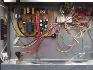
Inside view : Induction Heater

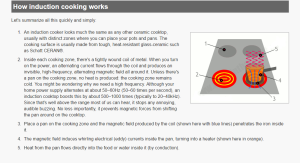
Induction cooking heats a cooking vessel by magnetic induction, instead of by thermal conduction from a flame, or an electrical heating element. Because inductive heating directly heats the vessel, very rapid increases in temperature can be achieved.

An induction cooker transfers electrical energy by induction from a coil of wire into a metal vessel that must be ferromagnetic. The coil is mounted under the cooking surface, and a high frequency (e.g. 24 kHz) alternating current is passed through it. The current in the coil creates a dynamic magnetic field. When an electrically conductive pot is brought close to the cooking surface, and the pan is thicker than the skin depth, the magnetic field induces large eddy currents in the pot. The eddy currents flow through the electrical resistance of the pot to produce heat; the pot then in turn heats its contents by heat conduction.

The cooking vessel typically needs to be made of a suitable stainless steel or iron. The increased magnetic permeability of the material decreases the skin depth, concentrating the current near the surface of the metal, and so the electrical resistance will be further increased. Some energy will be dissipated wastefully by the current flowing through the resistance of the coil. To reduce the skin effect and consequent heat generation in the coil, it is made from litz wire, which is a bundle of many smaller insulated wires in parallel. The coil has many turns, while the bottom of the pot effectively forms a single shorted turn. This forms a transformer that steps down the voltage and steps up the current. The resistance of the pot, as viewed from the primary coil, appears larger. In turn, most of the energy becomes heat in the high-resistance steel, while the driving coil stays cool.

Often a thermostat is present to measure the temperature of the pan. This helps prevent the pan from severely overheating if accidentally heated empty or boiled dry, but also can allow the induction cooker to maintain a target temperature.

capture


SOLAR LIGHTING SYSTEM

The aim of this circuit is to demonstrate how we can utilise solar light to electrify the remote areas, i.e., how we can store the solar energy and then use it for small-scale lighting applications.

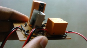
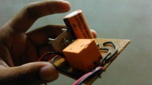
The DC voltage from the 10W, 12V solar panel is used to charge the battery and control the relay. Capacitor C connected in parallel with a 12V SPDT relay coil remains charged in daytime until the relay is activated. Capacitor C is used to increase the response time of the relay, so switching occurs moments after the voltage across it falls below 12V. The higher the value of the capacitor, the more the delay in switching.

During daytime, relay RL energises, the positive terminal of the battery is connected to the output of regulator IC 7808 (a 3-terminal, 1A, 8V regulator) via diode D and normally-open (N/O) contacts of relay RL1. Here we have used a 6V, 4.5Ah maintenance-free, lead-acid rechargeable battery. It requires a constant voltage of approx. 7.3 volts for its proper charging.
Even though the output of the solar panel keeps varying with the light intensity, IC 7808 (IC1) is used to give a constant output of 8V. Diode D causes a drop of 0.7V, so we get approx. 7.3V to charge the battery.

At night, there will be no generation of electricity. The relay will not energise and charging will not take place. The solar energy stored in the battery can then be used to light up the lamp. A 3W lamp glows continuously for around 6 hours if the battery is fully charged. Instead of a 3W lamp, you can also use a parallel array of serially connected white LEDs and limiting resistors to provide sufficient light for even longer duration.

SOLAR LIGHTING SYSTEM

Solar Home Light Circuit

DIY SOLAR LIGHTING SYSTEM

DIY SOLAR LIGHTING SYSTEM

DIY SOLAR LIGHTING SYSTEM

DIY SOLAR LIGHTING SYSTEM

SINGLE CHIP hi-fi AUDIO AMPLIFIER

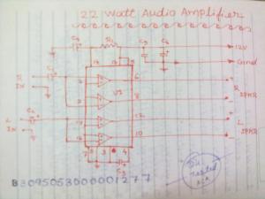
This is is a stereo power amplifier circuit works up to 22W on each channel. It will be 2x22W output. A few externel components required to support the main component of TDA1554. Heatsink on the power IC is a must to prevent overheating on the power IC. The chip should run cool enough to touch with the proper heatsink installed.Operated at 12 Volts and at about 5 Amps at full volume. Lower volumes use less current, and therefore produce less heat. Printed circuit board is preferred, but universal solder or perf board will do. Keep lead length short.


22 watts amp circuitcomponentssystem view

Hi-Fi 3D Surround Sound System

Surround system let the listener experience the sound reaching from three or more directions, which provides a more realistic audio environment.In fact, surround is the concept of expanding the spatial imaging of audio playback from one dimension(mono/left-right) to two or three dimensions. The surround sound effect can be achieved by processing an existing stereo sound track to add spaciousness and to make it originate it from outside the left/right speaker locations.

This slideshow requires JavaScript.

Creating surround sound

Surround sound is created in several ways. The first and simplest method is using a surround sound recording microphone technique, and/or mixing-in surround sound for playback on an audio system using speakers encircling the listener to play audio from different directions. A second approach is processing the audio with psychoacoustic sound localization methods to simulate a two-dimensional (2-D) sound field with headphones. A third approach, based on Huygens’ principle, attempts reconstructing the recorded sound field wave fronts within the listening space; an “audio hologram” form. One form, wave field synthesis (WFS), produces a sound field with an even error field over the entire area. Commercial WFS systems, currently marketed by companies sonic emotion and Iosono, require many loudspeakers and significant computing power.

The Ambisonics form, also based on Huygens’ principle, gives an exact sound reconstruction at the central point; less accurate away from center point. There are many free and commercial software available for Ambisonics, which dominates most of the consumer market, especially musicians using electronic and computer music. Moreover, Ambisonics products are the standard in surround sound hardware sold by Meridian Audio, Ltd. In its simplest form, Ambisonics consumes few resources, however this is not true for recent developments, such as Near Field Compensated Higher Order Ambisonics.[17] Some years ago it was shown that, in the limit, WFS and Ambisonics converge.[18]

Finally, surround sound also can be achieved by mastering level, from stereophonic sources as with Penteo, which uses Digital Signal Processing analysis of a stereo recording to parse out individual sounds to component panorama positions, then positions them, accordingly, into a five-channel field. There are however more ways to create surround out of stereo, for instance with routines based on the QS and SQ Quad routines, where instruments were in the studio divided over 4 speakers. This way of creating surround with software routines is normally referred to as “upmixing”.[19]

3D SURROUND SOUND SYSTEM BLOCK DIAGRAM

CIRCUIT SECTIONS

1. POWER SUPPLY
230v AC to 12 V DC
3A Transformer, 7812 regulator
IN5408*4 diodes
2. 3D FILTER
NJM 2702D-14pin DIP,two channel
3. AUDIO AMPLIFIER
TDA 1557Q-13pin SIL,Class B,20W*2, 4 ohm output.

Two channel sounds is the standard format for home stereo receivers,television and FM radio broadcast. When we listen to these two channels on separate speakers, it recreates the experience of being present at the event. Surround recordings can take this idea a step further by adding more audio channels so that the listener experience the sound reaching them from three or more directions which provides more realistic audio environment.

***

Ku Band LNB Disassembled

This slideshow requires JavaScript.

A low-noise block downconverter (or LNB) is the receiving device of a parabolic satellite dish antenna of the type commonly used for satellite TV reception. The device is sometimes wrongly called an LNA (Low-noise amplifier), LNC (for low-noise converter) or even LND (for low-noise downconverter) but as block-downconversion is the principal function of the device, LNB is the preferred term, although this acronym is often incorrectly expanded to the incomplete descriptions, low-noise block or low-noise block converter.[1][2] [3] [4]

The LNB is a combination of Low-noise amplifer, block downconverter and IF amplifier. It takes the received microwave transmission, amplifies it, downconverts the block of frequencies down to a lower block of intermediate frequencies where the signal can be fed to the indoor satellite TV receiver using relatively cheap cable.

The signal from the dish is picked up by a feedhorn and is fed to a section of waveguide. In this waveguide a metal pin, or probe, protrudes into the waveguide at right angles to the axis and this acts as an aerial, and feeds the signal to a printed circuit board in the LNB.

The LNB is usually fixed on the satellite dish framework, at the focus of the reflector, and it derives its power from the connected receiver. This phantom power is sent “up” the same cable that carries the received signals “down” to the receiver. The corresponding component in the transmit link uplink to a satellite is called a Block upconverter (BUC).


Ultra Low Cost HEARING AID using TDA 2822M Audio Amplifier IC

This low-cost, general-purpose electronic hearing aids works off 3V DC (2×1.5V battery). Transistor T1 and associated components form the audio signal preamplifier for the acoustic signals picked up by the condenser microphone and converted into corresponding electrical signals.

The medium-power amplifier section is wired around popular audio amplifier IC TDA2822M (not TDA2822). This IC, specially designed for portable low-power applications, is readily available in 8-pin mini DIP package. Here the IC is wired in bridge configuration to drive the 32-ohm general-purpose monophonic earphone.

The audio output of this digital hearing aides circuit is 10 to 15 mW and the quiescent current drain is below 1 mA. The circuit can be easily assembled on a veroboard. For easy assembling and maintenance, use an 8-pin DIP IC socket for TDA2822M.

This slideshow requires JavaScript.

Narianganam Church Website launched

Thanks to everyone for the experience with VERSION PLUS Team…Thanks to Riju Chettan and Vipin, Special thanks to Thomachen Chettan for giving this opportunity to participate with your big story…Keep Dreaming 🙂

www.narianganamchurch.org